Project: Home Automation Upgrade for CalSpa Hot Tub
1. Project Overview
Project Introduction:
I aim to retrofit my 2002 CalSpa hot tub with the ESP-WROOM-32 Development Board to enable advanced functionalities, including smart home integration with Alexa and a manual control interface. I received this tub for free. This endeavor requires meticulous planning, testing, and engineering insight to ensure functionality, safety, and ease of maintenance.
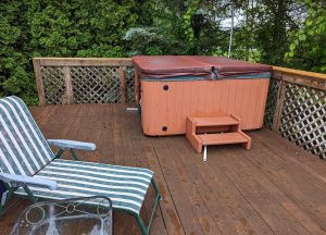
Calspa Hot Tub at My Home in Upstate NY
Objectives:
- System Retrofit: Implement the ESP-WROOM-32 Development Board to interface with the existing hot tub infrastructure.
- Alexa Integration: Develop a responsive system to handle voice-command interactions through Amazon’s Alexa platform.
- Manual Control Panel: Engineer a physical interface to provide users an alternative control mechanism, prioritizing usability and durability.
- Safety Protocols: Emphasize the safe interfacing of electrical components with the water-intensive environment of the hot tub. Simultaneously, incorporate cybersecurity measures to shield against potential threats.
- Efficiency: Target system optimizations to improve energy consumption without compromising performance.
- User Interface: Construct intuitive interfaces for both the Alexa integration and the manual control panel. Prioritize clarity, responsiveness, and user feedback.
- Maintenance & Scalability: Structure the integration in a modular manner, promoting easy troubleshooting, component replacements, and future upgrades.
Desired Outcomes:
- Voice-Activated Hot Tub Controls: Achieve reliable voice-command operations for controlling temperature, jet intensity, and lighting via Alexa.
- Functional Manual Interface: Deliver a tactile control panel that offers real-time status updates and direct system control.
- Safety Compliance: Guarantee a risk-free operation, having verified electrical safety under diverse test conditions.
- Optimized Energy Utilization: Document discernible energy conservation improvements when benchmarked against the original setup.
- User Experience: Capture user feedback to confirm enhanced interaction ease and system responsiveness post-upgrade.
- Forward Compatibility: Ensure the architecture is designed to accommodate upcoming technological advancements, minimizing future integration challenges.
In essence, this project’s goal is a technically sound upgrade of the CalSpa hot tub, merging the reliability of its original design with contemporary smart technologies.
2. Safety Precautions
Given the intrinsic risks associated with interfacing electricity and water, meticulous adherence to safety precautions is obligatory. The following outlines stringent protocols that must be observed throughout the project:
General Electrical Safety:
- Power Isolation: De-energize circuits when accessing or working on the system.
- Insulated Tool Utilization: Employ tools with insulated grips to preclude unintended circuit contacts.
- Wiring Inspection Protocols: Conduct routine assessments of wiring for signs of physical degradation or corrosion, particularly in moisture-prone zones.
- Load Specifications: Confirm component ratings align with system loads. Employ aptly-rated fuses and circuit breakers to counter potential overloads.
- Protective Equipment: Mandate the use of insulative gear, such as rubberized gloves and footwear, during system maintenance or adjustments.
Water-Electricity Interplay Protocols:
- Component Waterproofing: Guarantee comprehensive waterproofing measures for components with potential water exposure.
- Electrical Component Proximity: Institutionalize minimum safe distances for electrical fixtures from water sources to negate immersion risks.
- Drip Loop Mandate: Enforce a standard for cables connecting to the hot tub to incorporate drip loops, impeding water from capillary movement towards electrical junctions or devices.
- Moisture Checks: Establish a regular inspection schedule to identify and rectify moisture ingress near electrical installations.
- Dry-Operation Protocol: Prohibit any interaction with electrical controls with damp hands or from a wet standing position.
Grounding Imperatives:
- Shock Mitigation: Grounding provides an immediate discharge path for stray currents, substantially reducing electric shock hazards during faults.
- Component Safeguarding: A grounded system helps dispel potentially damaging overvoltages, e.g., lightning-induced surges.
- Voltage Stability: Grounding introduces a consistent reference point, ensuring voltage sources operate within defined parameters.
- Fault Recognition Mechanisms: A well-grounded system will interrupt its operation upon fault detection, thereby serving as a critical protective measure.
- Regulatory Adherence: Grounding practices should meet or surpass local electrical stipulations to ensure both safety and compliance.
It’s imperative to underscore that these are non-negotiable protocols and not merely suggestions. The confluence of water and electricity demands a stringent safety approach, where protocol adherence guarantees both equipment longevity and user safety
3. Initial Assessment
Before diving into the retrofitting and upgrading process, it’s crucial to conduct a comprehensive assessment of the existing system. This evaluation provides insight into the condition and functionality of the current components, enabling informed decisions about which parts can be retained and which should be replaced.
Existing System Components & Specifications:
- Control Board: The hot tub’s operations are currently facilitated by the Balboa Instruments C5000 control board from 2002, which orchestrates component functions.
- AC High Voltage Components:
- Main AC Inputs: The system utilizes 240v main AC inputs (Wht, Blk, Red, Grn).
- Pumps: Two distinct pumps are present: a primary 240v pump and a 120v circulation pump.
- Heater: The heating element is rated at 240v 5.5kw.
- Relays: A set of six 120v AC relays, directly soldered to the board, govern component switching functions.
- AC Low Voltage Components:
- Transformer: A unit that steps down voltage from 110v to 12v.
- Spa Lights: Operating at 12v AC.
- Sensors: The suite includes a temperature sensor, hi-limit/freeze sensor, and vacuum switch.
- Control Panel: The present manual interface.
Existing Wiring Diagram

CS5000 System Wiring Diagram (12/19/2002). Balboa Instruments Incorporated
Identifying Components to be Retained:
- Pumps: Retention of both pumps (240v and 120v) is advised, contingent on their operational health. While their primary functionality remains unchanged, control interfacing may be updated.
- Heater: If the 240v 5.5kw heater exhibits optimal functionality, it should be conserved and interfaced with the modern control system.
- Sensors: Key sensors, contingent on their operational status, should be preserved due to their critical safety role.
- Spa Lights: Retention is advisable unless there’s a requisition for a design evolution or LED transition.
Identifying Components to be Replaced:
- Control Board: The Balboa Instruments C5000, despite its durability, necessitates replacement due to its obsolescence in line with ESP-WROOM-32 Development Board integration and smart home objectives.
- Relays: The inherent 120v AC relays mandate a switch to contemporary, modular systems that cater to enhanced adaptability, streamlined maintenance, and compatibility.
- Control Panel: Supersedence of the current control panel with an advanced manual control interface is paramount to ensure modern user interactions.
- Transformer: Evaluating its operational efficacy and potential efficiency gains, a transition from the existing 110v to 12v transformer to a contemporary unit might be prudent.
In synthesis, this preliminary evaluation elucidates the extant system’s status, fostering informed decisions for ensuing project phases. The demarcation between preserved and upgraded components establishes the retrofitting roadmap.
4. Hardware Components
The tangible elements delineated herein comprise the infrastructural core of the CalSpa hot tub system upgrade, emphasizing efficiency, interoperability, and durability.
Control Hardware:
ESP-WROOM-32 Development Board Specifications & Overview: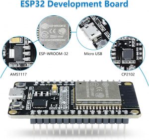
The ESP-WROOM-32 is a versatile board, boasting both Wi-Fi and Bluetooth capabilities. Key specifications include:
- CPU: Xtensa dual-core 32-bit LX6.
- Frequency: Max 240 MHz.
- RAM: 520 KB SRAM.
- Wireless: 2.4 GHz Wi-Fi/Bluetooth dual-mode.
- I/O: 30 GPIOs; functions: ADC, capacitive touch, GPIO, PWM, etc.
- Compatibility: Arduin, NodeMCU, MicroPython.
Selection of Relays (both solid state and electromagnetic):
- Solid State Relays (SSRs): Ideal for frequent switching applications due to non-mechanical components. Notable attributes include rapid response and longevity. Consider thermal management solutions.
- Electromagnetic Relays (EMRs): Mechanical in operation, they’re cost-effective, adept at high currents, and exhibit lower thermal output. Wear is a concern with regular actuations.
- Optimal Configuration: A hybrid approach: SSRs for high-frequency tasks (lights) and EMRs for high-load components (pumps/heaters).
Given the hot tub’s requirements, a combination of both can be optimal: SSRs for components like lights that might require frequent switching and EMRs for components like pumps and heaters.
Power Supply Units & Step-down Converters:
- Power Supply Units (PSUs): Prioritize stability and integrated protection (overcurrent, overvoltage, short-circuit).
- Step-down Converters: Essential for voltage regulation across components. Efficiency is paramount.
Sensors:
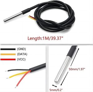
Waterproof DS18B20 Temperature Sensor
Waterproof DS18B20 Temperature Sensor:
- Function: Water temperature monitoring.
- Precision: ±0.5°C (-10°C to +85°C range).
- Output: Digital; 1-Wire interface.
- Build: Stainless steel encased.
Hi-Limit/Freeze Sensor & Vacuum Switch Specifications:
- Function: Hi-limit and freeze sensors for thermal management; vacuum switch for water flow.
- Output: Binary based on operational thresholds.
Manual Control Panel:
Panel Design & Layout:
- Size: Compact enough for convenience yet large enough to display all controls clearly.
- Material: A corrosion-resistant material, preferably with UV protection to prevent wear due to sunlight.
User Interface: Buttons, Dials, and Indicators:
- Buttons: For functions like power on/off, jet controls, and lighting. Ensure tactile feedback.
- Dials: For granular control over functions like temperature.
- Indicators: LEDs or display panels indicating the hot tub’s status, temperature, and any potential alerts.
Wiring & Integration with Main System:
- Wiring: Use waterproof and corrosion-resistant wiring. Ensure wires are appropriately labeled for easy troubleshooting.
- Integration: The panel should interface seamlessly with the ESP-WROOM-32 board, ensuring immediate response to user inputs.
Placement & Installation Considerations:
- Placement: Locate the panel at a convenient height and location for users, ideally where it’s shielded from direct rain or sunlight.
- Installation: Ensure secure mounting, and consider easy access for potential future maintenance.
Enclosures:
Waterproof & Humidity-resistant Selection:

Suggested: TICONN Waterproof Electrical Junction Box IP67 ABS Plastic Enclosure with Hinged Cover with Mounting Plate, Wall Brackets, Cable Glands (Clear, 8.7″x6.7″x4.3″)
- Material: Consider materials like ABS plastic or stainless steel that offer durability, water resistance, and protection from UV rays.
- Seals: Ensure enclosures have tight seals to prevent moisture ingress.
Placement & Accessibility Considerations:
- Location: Place enclosures where they are shielded from direct environmental factors but remain accessible for maintenance or upgrades.
- Accessibility: Ensure that while the enclosures are secured against unauthorized access, they can be easily opened for authorized maintenance or upgrades.
To recap, this hardware framework, given prudent selection, integration, and installation, will be instrumental in attaining the retrofit project’s longevity and efficacy goals. An emphasis on quality, positioning, and safety ensures the desired performance and resilience.
5. Integration with Alexa & Home Automation Platforms
To enhance user experience, this section delves into the integration of the CalSpa hot tub with Alexa and other contemporary home automation systems. By harnessing voice commands and remote access, we can achieve seamless spa management.
Alexa Integration Platforms:
Sinric Pro:
- Function: Allows ESP-WROOM-32 to emulate diverse smart devices, facilitating Alexa integration.
- Configuration: Utilizes an intuitive dashboard for device management; devices initialized in Sinric Pro are auto-detected in the Alexa app.
- Pricing: Free tier available; premium options for broader implementations.
ESP Alexa:
- Function: A dedicated library enabling ESP devices to interface with Alexa, expediting custom Alexa skill development.
- Configuration: Deployment via Arduino IDE to the ESP-WROOM-32 board enables device recognition within the Alexa app.
- Flexibility: Being library-based, it grants developers granular control over device behavior and customization.
Wi-Fi Connectivity & Security Considerations:
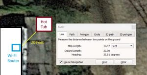
Hot Tub Proximity to Wi-Fi Router (2.4 GHZ)
- Connectivity Stability: Ascertain that the spa’s vicinity benefits from robust Wi-Fi coverage; deploy Wi-Fi range extenders if necessary.
- Encryption: Mandate WPA2 or advanced encryption for Wi-Fi, ensuring secure data interchange between the spa controller and home infrastructure.
- Network Isolation: To fortify security, deliberate on deploying a distinct Wi-Fi network or VLAN specifically for IoT integrations, thereby isolating primary home networks from potential threats.
- Firmware Maintenance: Periodically source and implement firmware updates for the ESP-WROOM-32 and related components, thereby safeguarding the system against recognized vulnerabilities.
In summary, careful and technical integration with Alexa and home automation systems not only augments user convenience but also streamlines spa operations within a broader home ecosystem. Ensuring robust connectivity and maintaining stringent security protocols are paramount.
6. Software & Programming
To ensure that the CalSpa hot tub functions correctly with both the manual control panel and Alexa integration, the software and programming aspect is crucial. This section provides a structured approach to building out the software logic, the design of the web interface, and the integration with Alexa.
Discrete Controls Logic:
- Power On/Off: Switch the entire system on or off.
- Temperature Setting: Adjust the water temperature, keeping within the safety limits.
- Jet Controls: Activate or deactivate water jets.
- Lighting: Toggle between different lighting modes or colors.
Software Stack & Libraries:
Platform:
- MicroPython: Given its compatibility with the ESP-WROOM-32 board, MicroPython offers a lightweight Python programming environment tailored for microcontrollers.
Libraries:
- machine Library: For handling pins and controls on the ESP32.
- umqtt Library: For MQTT communication, vital for interacting with platforms like Sinric Pro.
Example – Power Toggle:
from machine import Pin

# Defining the pin for power relay
power_relay = Pin(5, Pin.OUT) # assuming GPIO 5

def toggle_power():
    power_relay.value(not power_relay.value())
Web Interface Design & Features:
- Temperature Display: Show the current water temperature.
- Controls: Virtual buttons for power, jets, lighting, and temperature adjustment.
- Status Indicators: Display the status of heaters, jets, lights, etc.
Alexa Command List & Responses:
Command: “Alexa, turn on the hot tub.” Response: “Turning on the hot tub.”
Command: “Alexa, set the hot tub temperature to 100 degrees.” Response: “Setting the hot tub temperature to 100 degrees.”
Command: “Alexa, activate the hot tub jets.” Response: “Activating the hot tub jets.”
Fail-safe & Backup Logic:
- Temperature Overheat Protection: If temperature sensors detect water above safety limits, turn off the heater and notify the user.
- Loss of Connectivity: If connectivity with the board is lost, default to a safe mode, turning off potentially hazardous components like heaters.
Manual Control Panel Logic:
Input Detection & Processing:
Using the machine library’s Pin class, detect button presses or dial adjustments.
Example – Jet Control Button:
jet_button = Pin(12, Pin.IN, Pin.PULL_UP)  # assuming GPIO 12

def jet_control_callback(pin):
    # logic for toggling jets
    pass

jet_button.irq(trigger=Pin.IRQ_FALLING, handler=jet_control_callback)
Display & Feedback Logic (LED indicators, etc.):
- LEDs: Use LEDs to indicate the status of different components. For example, a green LED for power on, a blue LED when jets are active.
Integration with Main System Logic:
Ensure that manual controls override automated controls, giving users direct control in real-time. Implement a feedback mechanism, so if Alexa or the web interface gives a command, the manual panel displays the current status.
Example – Overriding Manual Controls with Alexa Commands:
def alexa_toggle_power():
    # Check if manual override is active
    if not manual_override_active:
        toggle_power()
In conclusion, building a robust software infrastructure is vital for the seamless and safe functioning of the hot tub system. Whether it’s through direct manual controls, voice commands via Alexa, or a web interface, ensuring a responsive and user-friendly experience is key. Proper fail-safe measures and feedback systems further enhance reliability and user confidence.
7. Testing & Quality Assurance
Ensuring that the upgraded CalSpa hot tub performs efficiently, safely, and consistently requires rigorous testing and quality assurance. By systematically validating each component, the integrated system, and user interfaces, we can ensure not only proper functioning but also a high-quality user experience. This section outlines the testing methodologies and strategies we will adopt.
Component-wise Testing:
- ESP-WROOM-32 Development Board: Test its connectivity, signal strength, and responsiveness. Ensure firmware updates are applied successfully, and board reboots as intended.
- Relays: Validate that they can successfully switch on/off and can handle the power requirements. Test their response time and consistency.
- Power Supply Units & Converters: Ensure the right voltage and current are being supplied, and there’s no fluctuation that could harm other components.
- Sensors: For the DS18B20 temperature sensor, Hi-Limit/Freeze Sensor, and Vacuum Switch, ensure accurate readings are being recorded, and there’s no lag in transmitting this data.
- Manual Control Panel: Test each button, dial, and indicator. Ensure responsiveness and durability.
Integrated System Testing:
- Power-Up Sequence: Verify that when powered on, the system initiates in the right sequence, activating the necessary components and establishing necessary connections.
- Command Processing: Check that commands from the manual panel, web interface, and Alexa are processed correctly and that one can override the other based on the hierarchy established.
- Fail-Safe Responses: Simulate failures such as loss of connectivity, overheating, or power fluctuations. Ensure that the system reverts to a safe mode as intended.
Safety Testing & Simulations:
- Water-Electricity Interaction: While the system is designed to avoid any direct interaction between water and electricity, simulate scenarios where water might come into contact with electrical components. The system should immediately shut down in such cases.
- Overheating: Simulate scenarios where the heater is left on beyond safety limits. The system should trigger an automatic shutdown and alert the user.
- Overcurrent & Overvoltage: Test the system’s response to sudden surges in power. Components should remain unaffected, and the system should ideally revert to a safe mode.
User Testing (Ease of Use, UX/UI):
- Interface Usability: Have users of varying tech-savviness interact with the manual control panel and the web interface. Collect feedback on intuitiveness, ease of use, and clarity.
- Voice Command Processing: Ask users to give a variety of commands to Alexa, including those not directly related to the hot tub. Ensure that only relevant commands are processed, and the responses are accurate.
- Feedback Mechanisms: Validate that feedback mechanisms (LEDs, alerts on the web interface, Alexa responses) are clear and helpful.
- Overall Experience: Collect feedback on the overall user experience, including any delays they might have noticed, any features they found redundant, or anything they felt was missing.
In wrapping up, testing and quality assurance are as crucial as the development phase. They ensure that all the hard work put into design and integration results in a product that’s not only functional and efficient but also safe and user-friendly. Regular iterations based on testing outcomes will lead to a refined final product.
8. Backup & Fail-safes
Ensuring the safety and reliability of the upgraded CalSpa hot tub is of paramount importance. The combination of electricity and water can pose significant risks if not carefully managed. As such, the design and integration of backup systems and fail-safe mechanisms are crucial to preemptively address potential failures, ensuring the protection of both the equipment and users. This section will detail the backup and fail-safe strategies adopted.
Manual Overrides:
- Priority Assignment: Manual controls should always have the highest priority, overriding any automated or voice-activated commands. In any scenario where there is a discrepancy between manual input and automated instructions, the system should default to the manual setting.
- Easy Access: All manual override controls, including buttons or switches, should be easily accessible and clearly marked. They should not require any specialized knowledge to operate.
- Instantaneous Response: Upon activating a manual override, the system should respond instantaneously, without any noticeable delay.
System Redundancies:
- Dual Sensors: Implementing dual sensors, especially for critical components like temperature sensing, will ensure that even if one fails, the other can provide accurate readings. The system should alert the user if there’s a discrepancy between the two.
Optional Redundancies:
- Backup Power Supply: A secondary power supply or a battery backup ensures that essential safety components, like alarms or emergency cut-offs, remain operational even in the event of a primary power failure.
- Connectivity Redundancy: Consider adding a secondary connectivity method, such as a cellular backup, ensuring that even if the primary Wi-Fi connection is lost, critical alerts can still be sent to the user.
Emergency Cut-offs & Alarms:
- Overheat Protection: If the water temperature exceeds safe limits, the system should automatically shut off the heater and activate an alarm, both audibly and visually. If integrated, Alexa can also provide an audible warning.
Optional Cut-Offs:
- Electrical Anomalies Detection: Employ sensors that detect any electrical anomalies, such as overcurrent or shorts. In such scenarios, an immediate cut-off should be triggered, isolating the affected component or shutting down the entire system if necessary.
- Water Contact Sensors: Place sensors in areas where water should not be present. If these sensors detect moisture, the system should trigger an alarm and potentially cut off power to vulnerable components.
- User Alerts: In the event of any fail-safe being triggered, users should be immediately alerted. This can be achieved through flashing LEDs, audible alarms, push notifications on their mobile device, or voice alerts through Alexa.
To conclude, the design and implementation of backup and fail-safe systems are not just supplementary; they’re integral to the overall functioning and safety of the CalSpa hot tub. By proactively addressing potential issues and implementing mechanisms to combat them, we’re ensuring a safe and enjoyable experience for the user, while also safeguarding the longevity and reliability of the system.
9. Implementation
The implementation phase is the hands-on culmination of the planning, design, and development processes. It’s imperative to ensure that every component is installed correctly and safely to achieve the desired functionality. This section will guide you through the systematic implementation of the project, from the step-by-step installation process to the intricate wiring details.
Step-by-step Installation Process:
- Preparation:
- Ensure the hot tub is powered off and disconnected from its power source.
- Clear the work area and have all necessary tools and components on hand.
- Familiarize yourself with the existing setup and the new components.
- Component Removal:
- Carefully remove the old Balboa Instruments C5000 control board.
- Label and safely set aside components that will be retained.
- ESP-WROOM-32 Board Installation:
- Mount the board inside a protective casing, ensuring it’s adequately ventilated.
- Position it close enough to the main system but avoid areas prone to excessive humidity.
- Relay & Power Supply Installation:
- Install the selected relays in line with the pumps, heaters, and other components.
- Ensure the power supply units and step-down converters are securely mounted and easily accessible.
Wiring Diagrams & Schematics:
- Main Power:
- Connect the 240v Main AC Inputs (Wht, Blk, Red, Grn) through the main relay.
- Pumps & Heater:
- Connect the 240v pump, 120v circulation pump, and the 240v 5.5kw heater through their respective relays, ensuring each relay matches its power requirements.
- Low Voltage Components:
- Use the step-down converter to supply 12v for the spa lights and the control panel.
- Ensure the temperature sensor, hi-limit/freeze sensor, and vacuum switch are correctly wired to the ESP32 inputs.
Note: A detailed schematic diagram with color-coded wiring will aid in minimizing mistakes during this intricate step.
Enclosure Setups & Installation:
- Selection:
- Choose waterproof and humidity-resistant enclosures for all electronic components, ensuring they have adequate ventilation.
- Installation:
- Mount enclosures in easily accessible areas while avoiding direct exposure to water splashes or extreme temperature fluctuations.
- Ensure all wiring entering or exiting the enclosures has waterproof grommets or seals.
- Maintenance Access:
- Position enclosures such that they can be easily opened or removed for maintenance and updates.
Manual Control Panel Installation Steps:
- Positioning:
- Determine an accessible yet protected location for the manual control panel, preferably where users can see the status indicators clearly.
- Mounting:
- Securely mount the panel using appropriate fixtures. Ensure that it’s stable and resistant to any mild external force.
- Wiring:
- Connect the control buttons, dials, and indicators to the ESP-WROOM-32 board, ensuring wires are neatly bundled and protected against wear and tear.
- Use color-coded wiring and connectors for easier troubleshooting and future maintenance.
- Testing:
- Once installed, perform a preliminary test to ensure all buttons, dials, and indicators function as intended.
To wrap up, the implementation process is a blend of careful planning and precise execution. Always refer back to schematics and notes during installation, and ensure safety precautions are adhered to throughout. After the initial setup, conduct a thorough testing phase to ensure all components interact seamlessly.
10. Detailed System Wiring and Integration Guide
Wiring the system is a meticulous process, demanding a systematic approach, precision, and a keen eye for detail. Below is a structured step-by-step guide to wire and integrate the entire CalSpa hot tub upgrade system using the ESP-WROOM-32 development board and associated components.
Prerequisites:
Ensure you have the following tools and materials:
- A soldering iron and solder
- Wire strippers
- Multimeter
- Heat shrink tubing
- Screwdrivers
- Suitable gauge wire (consider color-coding for clarity)
- Wire connectors or terminal blocks
Step-by-Step Guide:
1. Setting Up the ESP-WROOM-32 Development Board:
- Place the ESP-WROOM-32 on a non-conductive surface or mount it on a baseplate.
- Use the wire stripper to prepare your wires. Strip about 5mm off the ends.
2. Connecting the Relays:
For Solid State Relays (SSRs):
- Connect one end of a wire to a GPIO pin on the ESP32.
- Connect the other end of the wire to the control/input terminal of the SSR.
- Connect the ground of the SSR to the ground (GND) of the ESP32.
For Electromagnetic Relays (EMRs):
- Connect the base of your transistor (e.g., 2N2222) to a GPIO pin on the ESP32 using a 1kΩ resistor.
- Connect the emitter of the transistor to the ground (GND) of the ESP32.
- Connect the collector of the transistor to one end of the relay coil.
- Connect the other end of the relay coil to your VCC (usually 5V or 3.3V, based on the relay’s specifications).
- Attach the diode (e.g., 1N4007) across the relay coil terminals, ensuring the cathode (the stripe side) is on the VCC side.
3. Wiring Power Supply Units (PSUs) & Step-down Converters:
- Connect the input of your step-down converter to the PSU’s output.
- Ensure the output voltage from the step-down converter matches the ESP32’s requirements (3.3V).
- Connect the ESP32’s VCC and GND pins to the output of the step-down converter.
4. Wiring the Sensors:
Waterproof DS18B20 Temperature Sensor:
- Connect the VCC (usually red wire) of the DS18B20 to 3.3V on the ESP32.
- Connect the GND (usually black wire) to the ground of the ESP32.
- Connect the data wire (usually yellow or white) to any GPIO pin on the ESP32. Place a 4.7kΩ pull-up resistor between VCC and the data line.
Hi-Limit/Freeze Sensor & Vacuum Switch:
- Generally, these sensors provide binary outputs. Connect the output of the sensors to the ESP32 GPIO pins.
- Ensure to connect the sensor’s GND to the ESP32’s GND.
5. Manual Control Panel Integration:
Buttons, Dials, and Indicators:
- Connect the buttons to GPIO pins on the ESP32 and the ground, ensuring you utilize pull-up or pull-down resistors as needed.
- If using potentiometers (for dials), connect one outer pin to 3.3V, the other outer pin to GND, and the middle pin to a GPIO configured as an ADC.
- For indicators, connect LEDs through appropriate resistors (e.g., 220Ω for a typical LED) to GPIO pins and GND.
6. Ensuring Wi-Fi Connectivity:
- Place the ESP32 in a location where it has a strong Wi-Fi signal. Consider the use of Wi-Fi extenders if there are connectivity issues.
7. Enclosures:
- Once all components are wired, encase them in their respective waterproof and humidity-resistant enclosures. Ensure tight seals but also maintain accessibility for future maintenance or adjustments.
Final Checks:
- Before powering on, ensure all connections are tight and correct. Use the multimeter to check for any short circuits.
- Power on the system and test each component, starting from the ESP32, checking relay function, sensor outputs, and manual control responsiveness.
- Ensure that Wi-Fi connectivity is stable and the ESP32 connects seamlessly to the network.
11. Software Application Design for CalSpa Hot Tub Control
The software application for controlling the CalSpa hot tub using the ESP32 is central to achieving the desired user experience and functionality. Here’s an exhaustive outline of the software design:
I. Software Overview:
- Purpose: To control and monitor the CalSpa hot tub via manual inputs, Alexa voice commands, and potentially other home automation systems.
- Platform: ESP32 firmware, integrating with cloud-based platforms for Alexa and other home automation systems.
- Languages: Primarily C++ (for ESP32), Python or JavaScript (for web-based interfaces or server-side integrations).
II. Software Components:
- Main Control Logic:
- Processing input from sensors.
- Controlling relays for heaters, pumps, and lights.
- Interacting with manual controls.
- Web Interface:
- For remote monitoring and control.
- Displaying real-time data from sensors.
- Alexa Integration Layer:
- Handling voice commands.
- Sending feedback/responses to Alexa.
- Backup & Fail-safe Logic:
- Handling unexpected scenarios or failures.
- Ensuring safe defaults.
- Logging and Diagnostics:
- Recording system events.
- Aiding in troubleshooting and maintenance.
III. File Structure:
- main.cpp – Core logic and ESP32 setup.
- sensors.h & sensors.cpp – Handling all sensor data.
- controls.h & controls.cpp – Relays and manual control processing.
- web_interface.h & web_interface.cpp – Web-based controls and displays.
- alexa_integration.h & alexa_integration.cpp – All functions related to Alexa control.
- failsafe.h & failsafe.cpp – Logic for handling failures and safe defaults.
- logger.h & logger.cpp – System event recording and diagnostics.
IV. Code Overview:
- Initialization:
- Setup ESP32 Wi-Fi, GPIO configurations, and initial relay states.
- Initialize sensors and read initial values.
- Main Loop:
- Continuously read sensor values.
- Process Alexa or manual inputs.
- Control relays based on inputs.
- Update web interface with real-time data.
- Alexa Command Handling:
- Listen for specific voice commands.
- Process and execute respective actions.
- Send feedback to Alexa for voice confirmation.
- Fail-safe Checks:
- Monitor for any unsafe or unexpected conditions.
- Revert to safe defaults or shutdown in case of critical failures.
V. Testing:
- Unit Testing:
- Test each function individually to ensure they perform as expected.
- Mock sensor inputs and check for expected outputs.
- Integration Testing:
- Test the flow of data and control between various components.
- Simulate various user inputs and monitor system response.
- Stress Testing:
- Check the system’s performance under heavy load or continuous operation.
- Monitor for any memory leaks or performance drops.
- Safety Testing:
- Simulate failure scenarios.
- Validate that fail-safes trigger correctly.
- User Acceptance Testing:
- Real-world testing by end-users.
- Gather feedback on functionality and user experience.
VI. Deployment:
- Firmware Upload:
- Compile and upload the code to the ESP32.
- Monitor for any initialization errors.
- Cloud Integration:
- Link the ESP32 with cloud services for Alexa or other home automation platforms.
- Ensure secure and stable connectivity.
- Updates and Maintenance:
- Implement a method for over-the-air (OTA) updates.
- Regularly review logs for any potential issues.
By meticulously planning the software design, coding, and testing phases, you’ll ensure the CalSpa hot tub system operates seamlessly, efficiently, and safely. The software is the bridge between the hardware components and the user’s desires, so it’s crucial that it’s robust, user-friendly, and reliable.
VII. Software File Components
This is the application code I plan on using. This will be modified as the project progresses.
main.cpp
/*
 * CalSpa Hot Tub Control using ESP32
 * Author: David Maiolo
 * Date: August 22, 2023
 */

// Include necessary libraries and headers
#include "Arduino.h"
#include "sensors.h"
#include "controls.h"
#include "web_interface.h"
#include "alexa_integration.h"
#include "failsafe.h"
#include "logger.h"

// Global variables and definitions
#define WIFI_SSID "Your_WiFi_SSID"
#define WIFI_PASSWORD "Your_WiFi_Password"

// Function prototypes
void setupWiFi();

void setup() {
    // Initialize serial communication for debugging
    Serial.begin(115200);

    // Initialize Wi-Fi
    setupWiFi();

    // Initialize sensors, controls, and other modules
    initSensors();
    initControls();
    initWebInterface();
    initAlexaIntegration();
    initFailSafe();
    initLogger();

    Serial.println("CalSpa Hot Tub Control Initialized!");
}

void loop() {
    // Continuously monitor and process data
    processSensors();
    processControls();
    updateWebInterface();
    handleAlexaCommands();
    checkFailSafes();
    logSystemData();
}

void setupWiFi() {
    // Connect to Wi-Fi
    Serial.print("Connecting to Wi-Fi...");
    WiFi.begin(WIFI_SSID, WIFI_PASSWORD);

    while (WiFi.status() != WL_CONNECTED) {
        delay(500);
        Serial.print(".");
    }

    Serial.println();
    Serial.print("Connected with IP: ");
    Serial.println(WiFi.localIP());
}
Please replace “Your_WiFi_SSID” and “Your_WiFi_Password” with your actual network credentials. This code provides a foundation for integrating each module we’ve outlined earlier.
It’s crucial to consult the documentation of libraries and components you’re using to ensure correct initialization and processing within the setup() and loop() functions. As you progress, we’ll flesh out each function in greater detail based on the libraries we choose and the specific functionality wedesire.
sensors.h
/*
 * sensors.h
 * Sensor Management for CalSpa Hot Tub Control using ESP32
 * Author: David Maiolo
 * Date: August 22, 2023
 */

#ifndef SENSORS_H
#define SENSORS_H

#include "Arduino.h"

// Sensor pin definitions (Modify according to your setup)
#define TEMP_SENSOR_PIN       34
#define HI_LIMIT_SENSOR_PIN   35
#define VACUUM_SWITCH_PIN     36

// Function declarations
void initSensors();
float readTemperature();
bool checkHiLimit();
bool checkVacuumSwitch();

#endif //SENSORS_H
We’ll likely need to integrate specific libraries, and further adjust the code depending on the exact sensors and their respective communication protocols.
sensors.cpp
/*
 * sensors.cpp
 * Sensor Management for CalSpa Hot Tub Control using ESP32
 * Author: David Maiolo
 * Date: August 22, 2023
 */

#include "sensors.h"
// If using a DS18B20 temperature sensor with a library like OneWire, include it here
// #include <OneWire.h>

void initSensors() {
    // Initialize sensor pins
    pinMode(TEMP_SENSOR_PIN, INPUT);
    pinMode(HI_LIMIT_SENSOR_PIN, INPUT);
    pinMode(VACUUM_SWITCH_PIN, INPUT);

    // If you have other initializations (like setting up OneWire for DS18B20), place them here.
}

float readTemperature() {
    // This is a placeholder. Actual code will depend on your temperature sensor and any library you use.
    // Assuming a DS18B20 sensor with OneWire library, it'd look something like this:
    // OneWire ds(TEMP_SENSOR_PIN);
    // ... Code to get temperature ...
    // return temperature;
    return 25.0; // For now, return a dummy temperature.
}

bool checkHiLimit() {
    // Read the hi-limit sensor. Depending on the sensor, you may need analog or digital read.
    int hiLimitState = digitalRead(HI_LIMIT_SENSOR_PIN);
    return hiLimitState == HIGH;
}

bool checkVacuumSwitch() {
    // Read the vacuum switch state.
    int vacuumSwitchState = digitalRead(VACUUM_SWITCH_PIN);
    return vacuumSwitchState == HIGH;
}
This code assumes we will be using digital sensors for the hi-limit and vacuum switch. If they provide analog values, we’ll replace digitalRead with analogRead.
For the DS18B20 temperature sensor, we may utilize OneWire and DallasTemperature libraries. If we decide to use this sensor, be sure to integrate the necessary library calls and logic in the provided functions.
We can adjust pin definitions according to our setup and incorporate error-checking where necessary.
controls.h
/*
 * controls.h
 * Control Management for CalSpa Hot Tub Control using ESP32
 * Author: David Maiolo
 * Date: August 22, 2023
 */

#ifndef CONTROLS_H
#define CONTROLS_H

#include "Arduino.h"

// Pin definitions for relays and other control elements (Modify according to your setup)
#define PUMP_RELAY_PIN        25
#define HEATER_RELAY_PIN      26
#define LIGHTS_RELAY_PIN      27
// ... Add other control pins as needed ...

// Function declarations
void initControls();
void turnOnPump();
void turnOffPump();
void turnOnHeater();
void turnOffHeater();
void turnOnLights();
void turnOffLights();
// ... Add other control functions as needed ...

#endif //CONTROLS_H
controls.cpp
/*
 * controls.cpp
 * Control Management for CalSpa Hot Tub Control using ESP32
 * Author: David Maiolo
 * Date: August 22, 2023
 */

#include "controls.h"

void initControls() {
    // Set control pins to OUTPUT mode
    pinMode(PUMP_RELAY_PIN, OUTPUT);
    pinMode(HEATER_RELAY_PIN, OUTPUT);
    pinMode(LIGHTS_RELAY_PIN, OUTPUT);
    // ... Initialize other pins as OUTPUT ...

    // Set initial states (all OFF)
    digitalWrite(PUMP_RELAY_PIN, LOW);
    digitalWrite(HEATER_RELAY_PIN, LOW);
    digitalWrite(LIGHTS_RELAY_PIN, LOW);
    // ... Set other pins to their initial states ...
}

void turnOnPump() {
    digitalWrite(PUMP_RELAY_PIN, HIGH);
}

void turnOffPump() {
    digitalWrite(PUMP_RELAY_PIN, LOW);
}

void turnOnHeater() {
    digitalWrite(HEATER_RELAY_PIN, HIGH);
}

void turnOffHeater() {
    digitalWrite(HEATER_RELAY_PIN, LOW);
}

void turnOnLights() {
    digitalWrite(LIGHTS_RELAY_PIN, HIGH);
}

void turnOffLights() {
    digitalWrite(LIGHTS_RELAY_PIN, LOW);
}

// ... Implement other control functions similarly ...
web_interface.h
/*
 * web_interface.h
 * Web Interface for CalSpa Hot Tub Control using ESP32
 * Author: David Maiolo
 * Date: August 22, 2023
 */

#ifndef WEB_INTERFACE_H
#define WEB_INTERFACE_H

#include "Arduino.h"
#include "ESPAsyncWebServer.h"

void initWebInterface();
void updateWebInterface();

#endif //WEB_INTERFACE_H
web_interface.cpp
/*
 * web_interface.cpp
 * Web Interface Management for CalSpa Hot Tub Control using ESP32
 * Author: David Maiolo
 * Date: August 22, 2023
 */

#include "web_interface.h"
#include "controls.h"
#include "sensors.h"

// Create an instance of the web server
AsyncWebServer server(80);  // HTTP server on port 80

void initWebInterface() {
    // Endpoint for turning on the pump
    server.on("/pump/on", HTTP_GET, [](AsyncWebServerRequest *request){
        turnOnPump();
        request->send(200, "text/plain", "Pump turned on");
    });

    // Endpoint for turning off the pump
    server.on("/pump/off", HTTP_GET, [](AsyncWebServerRequest *request){
        turnOffPump();
        request->send(200, "text/plain", "Pump turned off");
    });

    // ... Add more endpoints for other controls ...

    // Endpoint to get the current temperature
    server.on("/temperature", HTTP_GET, [](AsyncWebServerRequest *request){
        float temp = readTemperature();
        String response = "Current temperature: " + String(temp) + "°C";
        request->send(200, "text/plain", response);
    });

    // Start the server
    server.begin();
}

void updateWebInterface() {
    // If there's dynamic content or periodic updates needed for the web interface, implement them here.
    // This could be things like periodic AJAX updates or WebSocket data pushes.
}
You’ll need to include the ESPAsyncWebServer and its dependencies in your project. The Arduino IDE’s Library Manager is a good place to find and install these. If you use PlatformIO, these can be included in the platformio.ini file’s lib_deps section.
The code above provides a simple RESTful API. You can expand this by adding a full HTML interface, AJAX for periodic updates, or even WebSockets for two-way communication.
For Alexa integration with ESP32, you would typically use the “FauxmoESP” library. It emulates a Philips Hue light system, allowing you to control your ESP32 with voice commands via Alexa. For the sake of this example, I’ll illustrate how to set this up:
alexa_integration.h
/*
 * alexa_integration.h
 * Alexa Integration for CalSpa Hot Tub Control using ESP32
 * Author: David Maiolo
 * Date: August 22, 2023
 */

#ifndef ALEXA_INTEGRATION_H
#define ALEXA_INTEGRATION_H

#include "Arduino.h"
#include "fauxmoESP.h"

void initAlexa();
void handleAlexa();

#endif //ALEXA_INTEGRATION_
alexa_integration.cpp
/*
 * alexa_integration.cpp
 * Alexa Integration Management for CalSpa Hot Tub Control using ESP32
 * Author: David Maiolo
 * Date: August 22, 2023
 */

#include "alexa_integration.h"
#include "controls.h"

fauxmoESP fauxmo;

void initAlexa() {
    // Define the devices. For example, "Hot Tub Pump"
    fauxmo.addDevice("Hot Tub Pump");
    fauxmo.addDevice("Hot Tub Heater");
    fauxmo.addDevice("Hot Tub Lights");

    fauxmo.onSetState([](unsigned char device_id, const char * device_name, bool state, unsigned char value) {
        if (strcmp(device_name, "Hot Tub Pump") == 0) {
            if (state) {
                turnOnPump();
            } else {
                turnOffPump();
            }
        }
        else if (strcmp(device_name, "Hot Tub Heater") == 0) {
            if (state) {
                turnOnHeater();
            } else {
                turnOffHeater();
            }
        }
        else if (strcmp(device_name, "Hot Tub Lights") == 0) {
            if (state) {
                turnOnLights();
            } else {
                turnOffLights();
            }
        }
    });
}

void handleAlexa() {
    fauxmo.handle();
}
In order for this to function, you’ll have to integrate and initialize the Wi-Fi and the FauxmoESP library, ensuring they’re connected to the network.
Once you’ve set up the above code:
- Start your ESP32 and make sure it’s connected to Wi-Fi.
- Open the Alexa app on your phone or tablet.
- Navigate to the Devices tab.
- Click the “+” sign in the top right corner.
- Click “Add Device”.
- Click “Other”.
- Click “Discover Devices”.
- Wait for Alexa to find and show your devices.
- Now, you should be able to say commands like “Alexa, turn on Hot Tub Pump”!
This example focuses on the essential functions to get it running. Depending on your needs, you may want to expand or adjust the code. Make sure to install and include all necessary libraries, and remember to call handleAlexa() in the main loop to allow FauxmoESP to process requests.
The failsafe.h and failsafe.cpp modules will be designed to handle any malfunctions or unforeseen issues, ensuring the hot tub system remains safe and avoids damage or potential hazards.
failsafe.h
/*
 * failsafe.h
 * Fail-safe Mechanisms for CalSpa Hot Tub Control using ESP32
 * Author: David Maiolo
 * Date: August 22, 2023
 */

#ifndef FAILSAFE_H
#define FAILSAFE_H

#include "Arduino.h"

// Function declarations
void initFailsafe();
void checkFailConditions();
bool isSystemSafe();

#endif //FAILSAFE_H
failsafe.cpp
/*
 * failsafe.cpp
 * Fail-safe Mechanisms Implementation for CalSpa Hot Tub Control using ESP32
 * Author: David Maiolo
 * Date: August 22, 2023
 */

#include "failsafe.h"
#include "sensors.h"
#include "controls.h"

// Thresholds for fail-safe conditions
const float MAX_SAFE_TEMPERATURE = 40.0; // Example threshold in Celsius
const float MIN_SAFE_TEMPERATURE = 5.0;  // Avoiding freeze conditions

void initFailsafe() {
    // Any initialization for fail-safe mechanisms goes here
    // For example, set up interrupt handlers, timers, etc.
}

void checkFailConditions() {
    float currentTemperature = readTemperature();

    // If temperature exceeds safety thresholds, shut off heater and pump
    if (currentTemperature > MAX_SAFE_TEMPERATURE || currentTemperature < MIN_SAFE_TEMPERATURE) {
        turnOffHeater();
        turnOffPump();
        // Optionally, you can also raise an alarm or notification here.
    }

    // Add any other checks as per your setup, like water level, pH level, etc.
}

bool isSystemSafe() {
    float currentTemperature = readTemperature();

    if (currentTemperature > MAX_SAFE_TEMPERATURE || currentTemperature < MIN_SAFE_TEMPERATURE) {
        return false;
    }

    // Check other conditions as needed

    return true; // Returns true if all conditions are within safe ranges
}
This is a fundamental implementation of a fail-safe system. Depending on the sensors and safety requirements, you’ll need to add more conditions and checks. Always prioritize safety and thoroughly test your system under all possible conditions. Remember to call checkFailConditions() in your main loop or set it up with a timer interrupt to regularly monitor the system’s state.
For logging on an ESP32, we usually store logs temporarily in the Serial monitor for debugging or to an external storage (e.g., an SD card) if we want to keep records. This logger module will provide basic serial logging functionalities. If you want to expand it for SD card logging, additional methods and initializations would be required.
logger.h
/*
 * logger.h
 * Logging Module for CalSpa Hot Tub Control using ESP32
 * Author: David Maiolo
 * Date: August 22, 2023
 */

#ifndef LOGGER_H
#define LOGGER_H

#include "Arduino.h"

// Function declarations
void initLogger();
void logInfo(const char* message);
void logWarning(const char* message);
void logError(const char* message);

#endif //LOGGER_H
logger.cpp
/*
 * logger.cpp
 * Logging Module Implementation for CalSpa Hot Tub Control using ESP32
 * Author: David Maiolo
 * Date: August 22, 2023
 */

#include "logger.h"

void initLogger() {
    Serial.begin(115200);
    delay(10);  // Allow serial communication to initialize

    logInfo("Logger initialized.");
}

void logInfo(const char* message) {
    Serial.print("[INFO] ");
    Serial.println(message);
}

void logWarning(const char* message) {
    Serial.print("[WARNING] ");
    Serial.println(message);
}

void logError(const char* message) {
    Serial.print("[ERROR] ");
    Serial.println(message);
}
To use the logger, call initLogger() in the setup() function of your main script. When you want to log messages, use logInfo(), logWarning(), or logError() as appropriate. These will print messages to the Serial monitor which can be viewed in real-time when the ESP32 is connected to your development environment.
This is a simple logging system. For more advanced requirements like remote logging, SD card storage, or timestamping, you’d need to expand this system.

